
Table of Contents
Major Types of Structural Cracks Explained with Practical Examples
For any building or infrastructure project, structural cracks are not merely surface defects; they often signal serious underlying engineering issues within the structure. Engineers new to the site frequently mistake all cracks for the same type and initiate repairs without identifying the root cause. Consequently, the same crack often reappears after a few months.
An experienced civil engineer never makes a decision based solely on the appearance of a crack. Instead, they analyze factors such as the crack’s pattern, location, direction, width, and depth, as well as the structural member’s loading conditions and construction history. This analysis determines whether the crack is structural or non-structural and, if structural, identifies the actual cause.
In this article, we will explore the major types of structural cracks in detail, using practical examples. For each type of crack, we will discuss the formation mechanism, site symptoms, failure patterns, inspection methods, and prevention strategies, enabling junior engineers to develop a practical understanding alongside their theoretical knowledge.
Why Is It Important to Understand Structural Cracks?
A building’s lifespan does not depend solely on its design; construction quality, workmanship, curing, material selection, and maintenance play equally important roles.
Often, a structure’s design is perfectly safe, yet a minor error during execution at the site can lead to dangerous cracks later on.
Practical projects have shown that many structural failures originate from a small crack. If such a crack is identified and repaired at an early stage, future damage costing lakhs of rupees can be avoided.
This is why experienced consultants place great importance on crack mapping and periodic structural inspections.
Engineering Classification of Structural Cracks
It is not sufficient to classify structural cracks just by name or shape. Structural engineers generally analyze them on the basis of load transfer mechanism and stress condition.
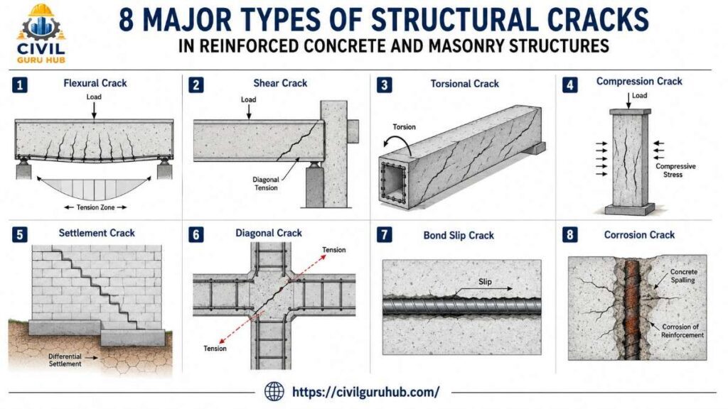
The following cracks are most commonly observed in reinforced concrete structures.
| Major Structural Crack | Main Stress |
|---|---|
| Flexural Crack | Bending Stress |
| Shear Crack | Shear Force |
| Torsional Crack | Twisting Moment |
| Compression Crack | Compression Failure |
| Settlement Crack | Differential Settlement |
| Diagonal Crack | Combined Stress |
| Bond Slip Crack | Steel-Concrete Bond Failure |
| Corrosion Crack | Reinforcement Expansion |
Flexural Cracks (Bending Cracks)
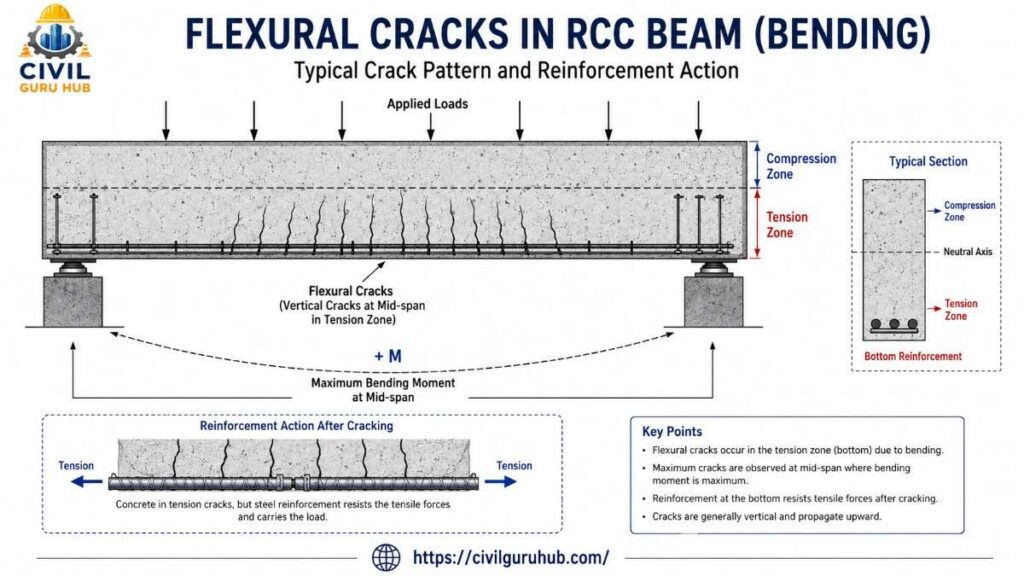
Flexural cracks are among the most frequently observed structural cracks in reinforced concrete structures. When the bending moment acting on a beam or slab exceeds the tensile strength of the concrete, cracks begin to develop in the concrete’s tension zone. While reinforcement steel bears the tensile force, concrete cannot resist tension; consequently, the first visible sign of distress appears in the form of a flexural crack.
On a construction site, if you inspect a beam in a residential building, you will generally observe vertical cracks on the beam’s bottom face. These cracks tend to develop less near the supports and more at the beam’s mid-span, as the maximum positive bending moment occurs there. The situation is reversed for cantilever beams; in such cases, the top face is in tension, and cracks originate from the upper surface.
During the inspection of a G+4 residential project in Odisha, vertical cracks approximately 0.4 mm wide were observed at the center of a beam. Initially, the contractor mistook them for shrinkage cracks. However, upon verifying the loading history and reinforcement drawings, it was discovered that the masonry load applied to the beam significantly exceeded the design specifications. Structural analysis subsequently identified a need for additional strengthening. This example illustrates that making decisions based solely on the visual appearance of a crack can be risky.
The width of flexural cracks generally fluctuates with the applied load. If a crack is active, monitoring is essential; this is typically done through periodic observations using crack gauges or tell-tale markers. If a crack continues to widen, a detailed structural evaluation is required.
Practical Site Indicators
- Vertical cracks on the bottom face of the beam
- Maximum crack density at mid-span
- Increase in crack width with increased loading
- Parallel cracks on the lower surface of the slab
Relevant Standards
- IS 456:2000
- IS 13920
- NBC 2016
- ACI 224R (Crack Control Guidance)
Shear Cracks
Shear cracks are considered the most dangerous crack pattern for reinforced concrete beams because their failure can generally occur without warning. Flexural cracks develop gradually, while shear cracks exhibit comparatively sudden propagation.
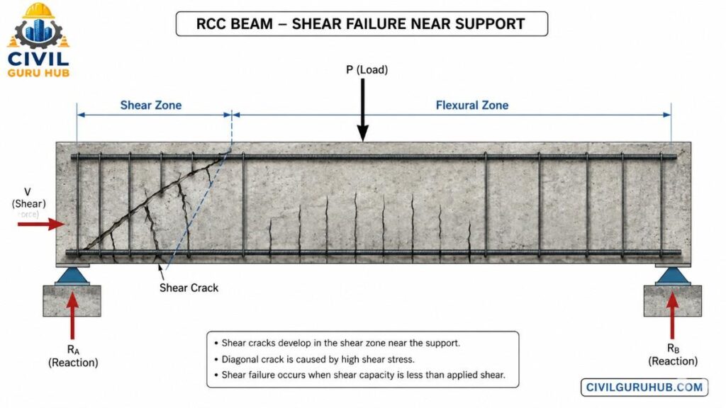
Shear forces are highest in the beam’s support region. When the concrete and shear reinforcement combined cannot resist the applied shear, inclined cracks begin to develop. These cracks typically appear in the beam’s web at angles of 30° to 45°.
During inspection on a bridge widening project, inclined cracks were observed near the supports. The contractor suggested epoxy injection only. However, the consultant verified the load history and reinforcement detailing. The investigation revealed that stirrup spacing was higher than provided in the drawing. This means the actual problem wasn’t the crack itself, but rather inadequate shear reinforcement. Simply filling the crack would have created a risk of future failure.
For this reason, an experienced structural engineer never simply repairs a crack. He first identifies the root cause.
Another unique characteristic of shear cracks is that they directly affect the beam’s load-carrying capacity. Therefore, treating them as cosmetic cracks is a major engineering mistake.
If a shear crack is active, the beam may require temporary unloading, shoring, and a detailed structural assessment.
To read more articles, check the following guides:
How to Identify Structural Cracks? Types, Causes and Repair Methods
What Are the Types of Foundations? A Complete Guide to Shallow and Deep Foundation 2026
Practical Site Indicators
- Inclined crack near support
- Beam web in diagonal pattern
- Crack width increases rapidly
- Cracks develop due to excessive deflection in the beam.
Relevant Standards
- IS 456:2000 (Shear Design)
- IS 13920
- ACI 318
- Eurocode 2
Torsional Cracks (Twisting Cracks)
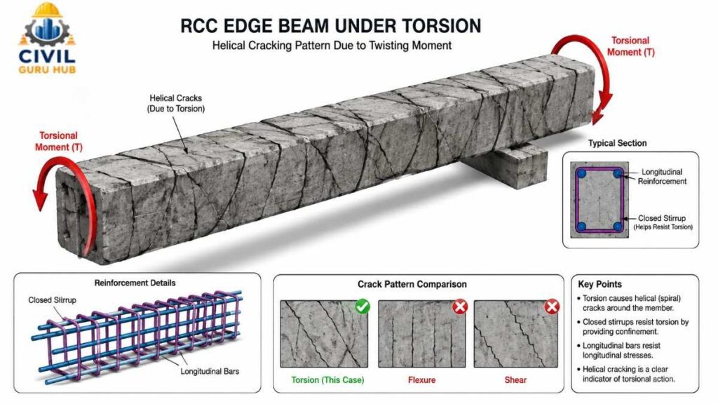
Torsional cracks develop in structural members subjected not only to bending or shear forces but also to twisting moments. In practical projects, this situation is commonly encountered in irregular building layouts, curved beams, edge beams, spiral ramps, balconies, and bridge girders.
Torsion is generated when a beam is subjected to eccentric loading or when the load is offset from the beam’s centroid. Concrete is unable to efficiently resist torsional tensile stresses; consequently, a helical or inclined crack pattern begins to develop around the member.
During an inspection of a commercial building’s parking ramp, inclined structural cracks were observed on both the side and bottom faces of a beam. Initially, these were mistaken for shear cracks. However, detailed analysis revealed that the beam was continuously experiencing torsional moments due to the ramp’s geometry. Inadequate reinforcement detailing led to the development of torsional distress.
Ignoring torsional cracks can invite future structural distress, as the failure of torsion reinforcement compromises the beam’s overall stability.
Field engineers should inspect not only the bottom face of the beam but also its side faces, torsion structural cracks often become visible on the side face first.
Practical Site Indicators
- Structural Cracks on both the side and bottom faces of the beam
- Spiral or inclined structural crack patterns
- Higher incidence in curved beams
- Common in edge beams and balcony beams
Relevant Standards
- IS 456:2000 (Torsion Design)
- ACI 318
- Eurocode 2
Compression Cracks
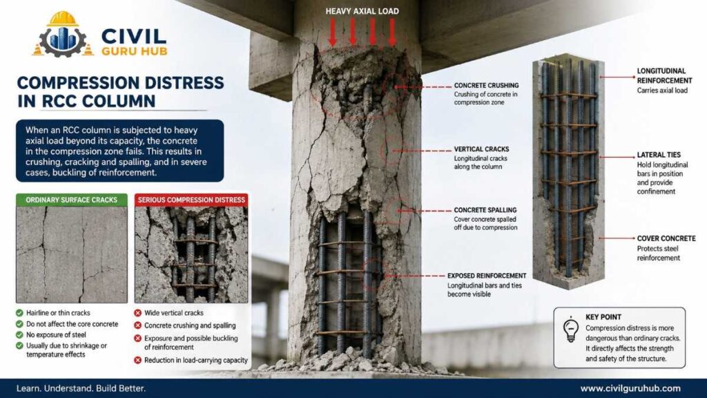
Compression cracks are generally observed in unreinforced concrete members where the compressive stress approaches or exceeds the concrete’s permissible capacity. Unlike flexural cracks, these cracks do not appear straight or distinct; they exhibit an irregular, crushing-type pattern and are often accompanied by concrete spalling.
The development of compression Structural cracks in columns is considered a serious warning sign. Symptoms of concrete crushing begin to appear if a column is overloaded, the concrete quality is poor, reinforcement detailing is incorrect, or damage occurs following an earthquake.
During the inspection of a column in an industrial warehouse, the detachment of concrete cover and vertical crushing cracks were observed. Initial investigations by the contractor attributed the issue merely to plaster damage; however, rebound hammer and core tests revealed that the concrete strength was significantly lower than the design grade. The column had to be strengthened using structural jacketing.
The most dangerous aspect of compression structural cracks is that they often develop in load-bearing members. Failure to undertake timely repairs and strengthening can increase the risk of progressive failure.
Therefore, a structural audit should be conducted immediately upon observing a crushing pattern in any column or heavily loaded wall.
Practical Site Indicators
- Concrete crushing
- Surface spalling
- Breaking away of concrete cover
- Exposure of reinforcement
- Vertical distress in the column
Relevant Standards
- IS 456:2000
- IS 15988 (Seismic Evaluation and Strengthening)
- NBC 2016
Settlement Cracks (Differential Settlement Cracks)
A settlement structural crack is a type of structural crack that often indicates an issue at the foundation level. Many junior engineers mistakenly dismiss these as mere plaster cracks, failing to realize that the actual problem lies in the foundation below. Consequently, repairing only the plaster without identifying the root cause is a waste of both time and money.
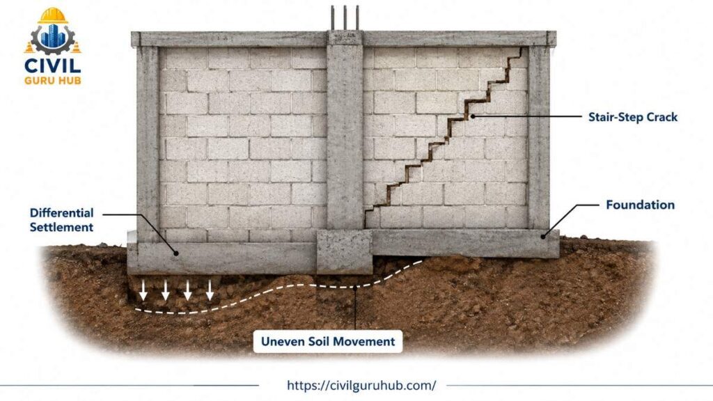
Settlement cracks develop when one part of a building settles more or less than another; this condition is known as “differential settlement.” If the entire building settles uniformly, structural cracks generally do not occur. Problems arise when the foundation settles unevenly.
In practical projects, various reasons for differential settlement are observed, such as loose soil remaining beneath the foundation, inadequate compaction, soil softening due to water leakage, nearby excavation, failure of underground utilities, or the shrink-swell behavior of expansive soil. In areas with clayey soil, significant soil movement is often noticeable between the rainy and summer seasons.
In a G+3 apartment project, stair-step pattern cracks were observed near the junction of the ground floor wall and beam. The contractor removed the plaster and refinished the surface, but the crack reappeared after just eight months. A geotechnical investigation revealed that the fill material beneath one corner of the building had not been properly compacted. As a result, the foundation settled unevenly, causing the crack to re-emerge. For this project, pressure grouting and foundation stabilization were required before the crack could be repaired.
The pattern of a settlement structural crack is generally not random. In masonry walls, it follows a zig-zag (stair-step) pattern, whereas in RCC members, diagonal or vertical cracks may appear. If doors and windows suddenly start jamming, the floor develops a slope, or a gap appears at the junction of the wall and slab, the possibility of settlement should not be ignored.
An experienced site engineer never begins repairs immediately upon spotting a settlement crack. First, crack mapping, a level survey, and a review of the foundation history are conducted. If the crack is active, a crack gauge is installed to monitor it over a period of weeks or months.
Practical Site Indicators
- Stair-step cracks in brick masonry
- Diagonal cracks at the junction of walls and columns
- Jamming of doors and windows
- Uneven floor levels
- Settlement of a building corner
Relevant Standards
- IS 1904 – Design and Construction of Foundations
- IS 6403 – Bearing Capacity of Shallow Foundations
- NBC 2016
- IS 456:2000
Diagonal Cracks
A diagonal crack is a structural crack pattern that typically develops not from a single cause, but from the combined effect of multiple stresses. Consequently, diagnosing this type of crack is relatively difficult. Diagonal cracks are often mistaken for shear cracks, even though the two exhibit different structural behaviors.
Diagonal structural cracks can appear in beams, walls, slabs, lintels, and masonry structures. They generally form at an angle between 30° and 60°, though the exact angle depends on loading conditions and stress distribution.
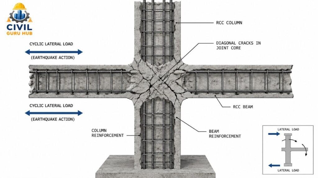
During the inspection for a seismic retrofitting project at a hospital building, diagonal cracks were observed near the beam-column joint. Initial inspection suggested they were ordinary shrinkage cracks; however, crack mapping revealed that diagonal tension had developed in the joint region due to cyclic loading during an earthquake. Had the cracks merely been filled, the underlying structural weakness would have remained unaddressed.
In masonry buildings, diagonal cracks frequently originate at the corners of window and door openings. This is caused by stress concentration; the corners of openings are naturally weak zones where tensile stress increases during load redistribution.
During a practical site inspection, an engineer should examine not only the direction of the structural crack but also its continuity pattern. If the crack is limited to the plaster, the repair approach differs; however, if the crack extends into the concrete core, a detailed structural assessment becomes mandatory.
Ignoring diagonal cracks can lead to future structural distress, particularly in buildings located in seismic zones.
Practical Site Indicators
- Inclined crack near the beam-column joint
- Crack originating from a window corner
- Diagonal pattern in a masonry wall
- Distress in the joint region following an earthquake
Relevant Standards
- IS 13920 – Ductile Detailing
- IS 1893 (Part 1) – Earthquake Resistant Design
- NBC 2016
To read more articles, check the following guides:
- What Are the 12 Types of Drain? A Complete Guide
- What Are the Types of Wearing Coat in Bridges? 10 Easy Explanations
- How Do Engineers Predict Box Culvert Failure? 7 proven Factors That Civil Engineer Must Know
- What Are Toe Wall and Breast Wall? Complete Comparison in 12 Points
Bond Slip Cracks (Reinforcement Bond Failure structural Cracks)
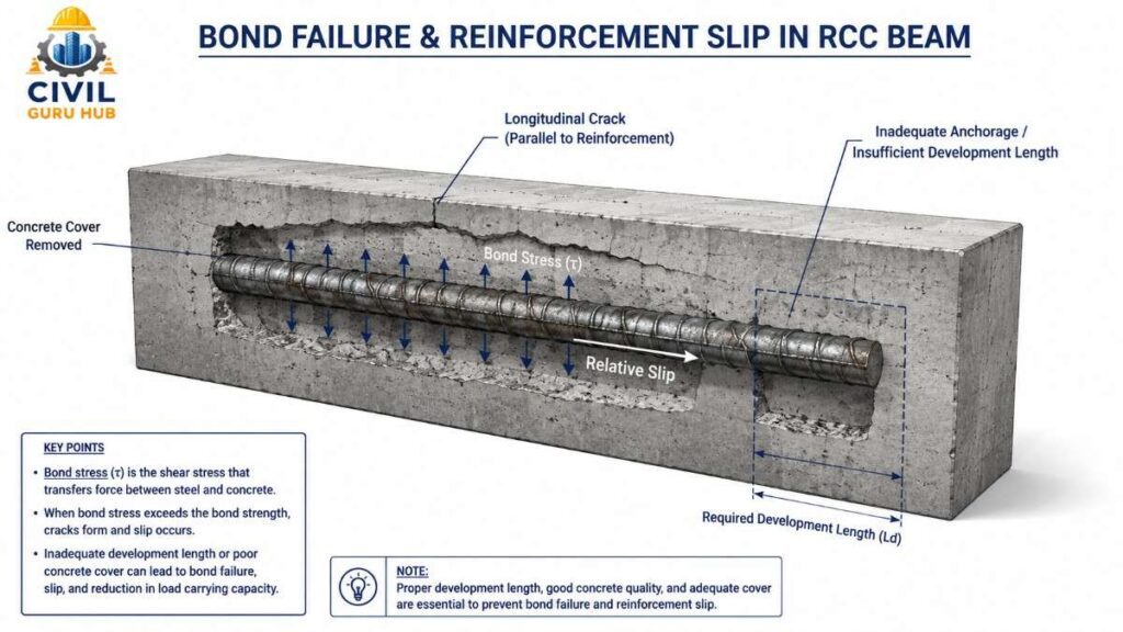
Concrete and reinforcement steel function as a composite structural member only when a proper bond develops between them. If this bond weakens for any reason, the reinforcement begins to slip, leading to the formation of bond slip cracks.
While these cracks are not as common as flexural or shear structural cracks, their occurrence directly affects the structure’s load transfer mechanism.
Common causes of bond failure include inadequate development length, insufficient anchorage, improper lap splices, honeycombing, poor compaction, and low-quality concrete. Often, reinforcement is not provided with the proper embedment specified in the drawings during site execution. Although no visible issues appear initially, cracks begin to develop as the load increases.
In an industrial shed project, a longitudinal structural crack was observed near the support of a roof beam. Upon removing the concrete cover during the investigation, it was discovered that the reinforcement bars had not been extended to the required development length. Consequently, the steel could not transfer the load effectively, resulting in bond failure.
Bond slip cracks generally develop parallel to the reinforcement. Often, the concrete cover begins to separate along with the crack. If the adhesion between the steel and concrete weakens, the reinforcement fails to transfer loads effectively.
Before undertaking repairs, experienced engineers often use tools such as reinforcement scanners, cover meters, and in some cases pull-out tests to evaluate the actual condition of the bond.
Practical Site Indicators
- Longitudinal structural cracks parallel to the reinforcement
- Separation of the concrete cover
- Cracks in the vicinity of honeycombing
- Signs of distress in the beam support region
Relevant Standards
- IS 456:2000
- IS 13920
- ACI 408
- ACI 318
Corrosion Cracks (Reinforcement Corrosion Cracks)
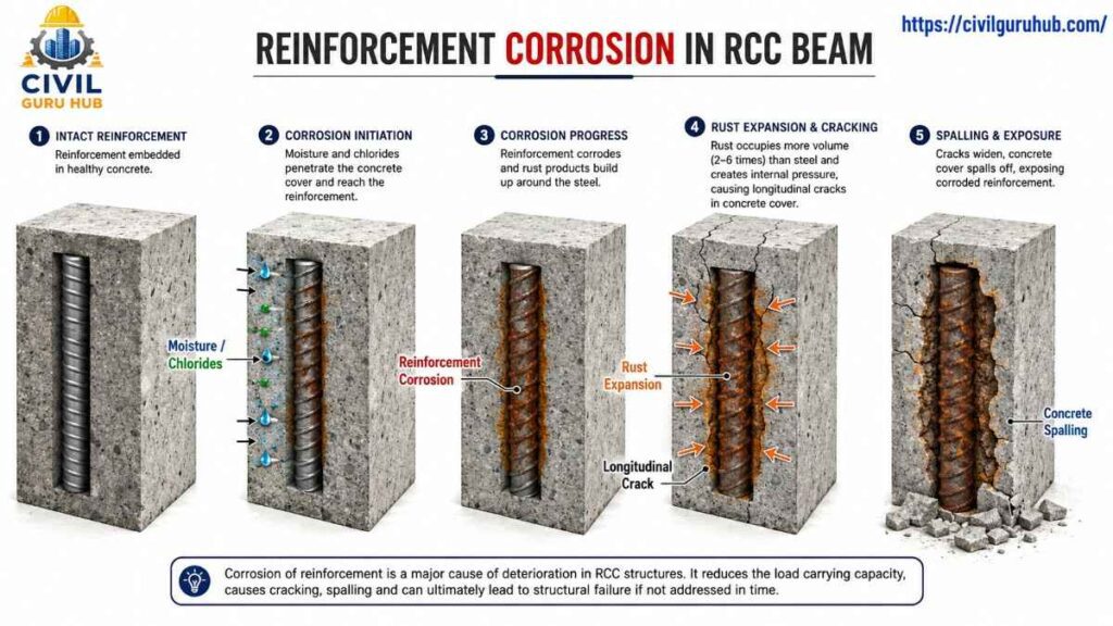
If any single type of structural crack is considered the most dangerous from a long-term durability perspective, it is the corrosion crack. The root cause of this crack is not the concrete itself, but the rusting process of the reinforcement steel.
Steel begins to rust when chloride attack, carbonation, or moisture penetration occurs around the reinforcement. The volume of rust is many times greater than that of the original steel. This expansion generates internal pressure within the concrete, and gradually, longitudinal cracks begin to appear on the surface.
Corrosion structural cracks are very common in coastal areas, marine structures, bridge decks, and water-retaining structures. If the concrete cover is inadequate or curing has been poor, moisture and oxygen reach the reinforcement quickly.
During the inspection of a highway bridge, structural cracks running parallel to the reinforcement were observed on the bottom face of a girder. Hammer sounding revealed hollow sounds at several locations. Upon removing the concrete, the reinforcement was found to be heavily corroded. Had only epoxy injection been performed, the crack would have reappeared within a few years. This project involved cleaning the corroded reinforcement, applying an anti-corrosion coating, and using polymer-modified repair mortar.
The biggest challenge with corrosion cracks is that the internal corrosion process has often been underway for years before a visible crack appears. This makes preventive maintenance crucial.
Practical Site Indicators
- Straight cracks parallel to the reinforcement
- Rust stains visible on the surface
- Concrete spalling
- Exposed reinforcement
- Hollow sound during hammer tapping
Relevant Standards
- IS 456:2000 (Durability Provisions)
- IS 9077
- ASTM C876 (Half-Cell Potential Test)
- ACI 222R (Corrosion of Metals in Concrete)
To read more articles, check the following guides:
- One Way Slab vs Two Way Slab: complete guide
- Toe Wall in Civil engineering : A complete guide
- what is Retaining Wall and Its Type: Complete Guide
A Practical Approach to Structural Crack Investigation
Merely observing a crack on-site does not constitute an engineering inspection. Investigation is a systematic process involving the evaluation of the crack’s location, direction, width, depth, and progression.
An experienced engineer typically divides the inspection into three stages:
Stage-1 Visual Inspection
Initially, crack mapping of the entire structure is conducted. Details such as the structural member affected, the direction of the crack, and its extent (length) are marked on the drawings.
Stage-2 Measurement
Crack width is measured using a crack width gauge or a digital microscope. If there is a suspicion that the crack is active, monitoring is carried out by installing a tell-tale gauge.
Stage-3 Detailed Investigation
If the crack is classified as serious, NDT (Non-Destructive Testing) and laboratory testing are performed.
Commonly used tests:
| Investigation Method | Purpose |
|---|---|
| Crack Width Gauge | Crack Width Measurement |
| Rebound Hammer Test | Surface Strength |
| UPV Test | Internal Concrete Quality |
| Core Test | Actual Concrete Strength |
| Cover Meter | Reinforcement Cover |
| Half-Cell Potential Test | Corrosion Assessment |
Crack Width Assessment (Practical Guideline)
The seriousness of a crack can be judged not only by its type but also by its width.
| Crack Width | General Observation |
|---|---|
| Less than 0.1 mm | Hairline Crack |
| 0.1 – 0.3 mm | Minor Structural Observation Required |
| 0.3 – 0.5 mm | Detailed Investigation Recommended |
| Above 0.5 mm | Immediate Structural Assessment Required |
Note: Acceptable crack width depends on the structure’s exposure condition, loading and durability requirement. Final assessment should always be done as per the design engineer’s recommendation and relevant code provisions.
See the technical videos to get better idea:
What Should an Engineer Check Before Undertaking Structural Crack Repair?
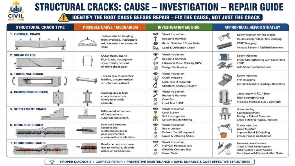
A common mistake novice engineers make on-site is rushing to repair a crack the moment they spot it. However, an experienced structural engineer does not merely repair the crack itself; instead, they aim to eliminate its root cause. If the underlying cause is not addressed, the crack may reappear after a few months or years, regardless of the quality of the epoxy or repair mortar used.
Before commencing repairs, it is crucial to determine whether the crack is “active” or “dormant.” An active crack is one that continues to change due to factors like load, temperature fluctuations, or structural settlement. A dormant crack, on the other hand, stabilizes after initially forming. Simply using epoxy injection on an active crack is often ineffective because the movement persists.
Next, factors such as the crack’s type, width, depth, and location, as well as the structural significance of the affected member and its load-bearing conditions, are analyzed. The same repair method cannot be applied across beams, slabs, columns, and footings; similarly, repair criteria differ between structures like coastal bridges and residential buildings.
Consider a practical example involving a commercial building where epoxy injection was performed on a beam, yet the actual issue was ongoing differential settlement. The crack reappeared just six months later. A permanent solution was achieved only after the foundation was stabilized and the crack was subsequently repaired. This example illustrates that proper diagnosis is the most critical step before undertaking any repair work.
Structural Crack Repair Methods – Which Method to Use When?
No single repair technique is suitable for every crack. The choice of repair method depends on the crack’s cause, width, structural significance, and durability requirements.
Epoxy Injection
Epoxy injection is one of the most common structural crack repair techniques. It is generally used for fine structural cracks that are dormant (inactive) and where the structural integrity of the member needs to be restored.
Epoxy is injected into the crack under pressure. It rebonds the crack faces and helps restore stiffness.
However, epoxy injection is effective only when crack movement has ceased. Injecting epoxy into active cracks or settlement cracks without addressing the root cause does not provide a long-term solution.
Cementitious Grouting
Cementitious grout is used when cracks are relatively wide or voids are present. This method is common in foundations, retaining walls, and mass concrete structures.
The grout fills the cracks and voids under pressure, thereby improving load transfer.
Polymer-Modified Repair Mortar
Simple crack filling is insufficient in cases where the concrete cover is damaged, reinforcement is exposed, or spalling is occurring.
In such situations, the damaged concrete is removed, the reinforcement is cleaned, and polymer-modified repair mortar is applied.
This method is frequently used for bridges, parking structures, and industrial buildings.
Steel Jacketing
Steel jacketing is an effective strengthening technique when the load-carrying capacity of a column or beam has significantly decreased.
Steel plates or sections are installed around the structural member, and composite action is achieved through grouting.
This repair provides structural strengthening rather than just a cosmetic fix.
RCC Jacketing
RCC jacketing is one of the most commonly adopted methods for strengthening existing buildings in India.
It involves adding extra reinforcement and concrete around an existing beam or column, thereby increasing both the cross-section and the load-carrying capacity.
RCC jacketing is also considered highly effective for earthquake retrofitting projects.
FRP Wrapping (Fiber Reinforced Polymer)
The use of FRP wrapping has increased significantly in recent years. Carbon Fiber Reinforced Polymer (CFRP) and Glass Fiber Reinforced Polymer (GFRP) sheets are wrapped around the structural member using epoxy.
The biggest advantage of this technique is that it adds very little dead load to the structure, and the installation process is relatively fast.
FRP strengthening is becoming increasingly popular for bridges, hospitals, heritage structures, and industrial buildings.
Common Site Mistakes During Structural Crack Repair
Practical projects have shown that structural crack failure is often caused not just by design issues, but also by improper execution of the repair. To complete the job quickly, many contractors simply apply surface putty or plaster. A few months later, the crack reappears; the owner often assumes the repair material was defective, whereas the actual issue lies in an incorrect diagnosis.
Another common mistake is injecting epoxy directly without first cleaning the crack. If dust, laitance, or moisture is present inside the crack, the epoxy cannot form a proper bond. Similarly, applying repair mortar without removing rust from the reinforcement can also lead to long-term failure.
Ignoring foundation settlement, merely covering up honeycombing, failing to monitor the crack, and neglecting curing after the repair are other frequently observed mistakes. An experienced engineer always carries out repairs with proper documentation and maintains records of pre- and post-repair inspections.
Expert Tips for Site Engineers
A skilled Site Engineer views a crack not merely as a defect, but as part of the structure’s “language.” A crack always signals the presence of some form of internal stress. If this signal is understood in time, major structural damage can be prevented.
Always use a scale alongside the subject when taking photographs during inspections to facilitate future comparisons. Maintain a crack mapping drawing. If a crack appears active, monitor it before proceeding with repairs. Do not make the mistake of increasing the load or finalizing a repair method for any major crack without the approval of a Structural Design Engineer.
Civil Engineering Interview Questions
- What is the practical difference between a flexural crack and a shear crack?
- What is the difference between an active crack and a dormant crack?
- How do you identify a corrosion crack?
- What causes inclined cracks to develop near beam supports?
- What is the permanent solution for settlement cracks?
- When should epoxy injection not be used?
- What is the difference between RCC jacketing and FRP wrapping?
- Which NDT tests are used for investigating structural cracks?
- How is crack width measured?
- What could be the root cause of concrete spalling?
Conclusion
Understanding the major types of structural cracks is not only important for Civil Engineering exams, interviews, or theoretical knowledge but is also a crucial part of the daily professional work of Site Engineers, Quality Engineers, Structural Engineers, and Project Engineers. While spotting a crack on a construction site is a common occurrence, not every crack signifies the same issue. Some cracks may be relatively minor, whereas others can indicate structural distress, excessive loading, differential settlement, shear failure, reinforcement corrosion, inadequate detailing, or durability issues.
Therefore, simply applying plaster, putty, mortar, or epoxy the moment a crack is spotted is not the correct engineering approach. First, one must observe the crack’s location, pattern, direction, width, length, depth, age, and progression. Subsequently, it is essential to understand the structural mechanism that caused the crack to develop. If necessary, measures such as crack monitoring, NDT testing, reinforcement assessment, concrete strength evaluation, foundation investigation, or detailed structural analysis should be undertaken.
The most important principle of this entire process is to identify the root cause before attempting repairs. If a crack has developed due to foundation settlement, merely filling the wall crack will not provide a permanent solution. If the concrete cover is cracking and spalling due to reinforcement corrosion, addressing the cause of the corrosion is necessary rather than just performing a surface repair. Similarly, in cases of shear or compression-related distress, cosmetic repairs do not resolve the underlying structural safety issues.
An experienced Site Engineer does not view a crack merely as a defect but interprets it as a warning signal regarding the structure’s behavior. The crack’s pattern, location, and progression help the engineer understand the type of stress or movement developing within the structure. By combining these practical observations with drawings, material records, construction history, loading conditions, and applicable standards, sound engineering decisions can be made.
If you observe a crack in an existing building, bridge, industrial structure, or RCC project, do not panic; instead, conduct a systematic inspection and, in cases of serious structural distress, seek an assessment from a qualified Structural Engineer. When selecting a repair method, one must consider the structure’s safety, durability, serviceability, and future performance.
Finally, always keep one principle in mind:
“Repair the cause of the crack, not the crack itself.”
When the actual cause of the crack is identified and properly controlled or eliminated, the repair ceases to be merely a temporary cosmetic fix; instead, it genuinely helps enhance the structure’s safety, durability, and service life. This is the approach that transforms a junior engineer—who might otherwise simply observe cracks—into a problem-solving Site Engineer.
About the Author
My name is Susanta Kumar Mohapatra. I am a Civil Engineering professional with over 11 years of practical experience in the construction and infrastructure sectors. I hold a B.Tech degree in Civil Engineering and an M.E. degree in Construction Management. Throughout my professional career, I have worked in key areas such as road construction, bridge projects, quality control, material testing, concrete mix design, highway engineering, quantity estimation, project planning, site execution, and construction management.
I launched CivilGuruHub.com with the aim of sharing my passion for Civil Engineering and my practical knowledge with a wider audience. The primary objective of this website is to provide practical, industry-oriented information in simple language to Civil Engineering students, site engineers, quality engineers, quantity surveyors, contractors, and construction professionals. Here, I publish detailed, original, and research-based articles on topics such as construction technology, concrete technology, highway engineering, structural engineering, material testing, IS codes, IRC codes, quantity surveying, estimation and costing, project management, tendering, and Civil Engineering calculators.
Alongside the website, I also run a YouTube channel named “The Civil Site,” where I explain practical site experiences, laboratory tests, construction techniques, engineering calculations, software tutorials, and technical concepts through easy-to-understand videos. My goal is to ensure that every student and engineer understands not just the theory, but also its practical application.
Additionally, I share educational content related to general knowledge, quizzes, and competitive exam preparation through my YouTube channel, “Daily IQ Hub.” The aim of this channel is to enhance viewers’ knowledge and strengthen their exam preparation.
I believe that a successful engineer is one who is always ready to learn and continuously updates their practical knowledge. With this mindset, I always strive to provide high-quality, reliable, practical, and industry-standard content through CivilGuruHub.com and my YouTube channels, enabling every reader and viewer to excel in their careers.
Thank you sincerely for your trust and support. I am confident that CivilGuruHub.com and my educational platforms will prove to be reliable companions in your learning journey and professional growth. If you wish to take your knowledge in the field of Civil Engineering to the next level, please continue to follow our articles and videos regularly. We will keep bringing you fresh, practical, and industry-focused content.
Frequently Asked Questions (FAQs)
Is every structural crack dangerous?
No. Not every structural crack is immediately dangerous, but every structural crack certainly requires an engineering investigation.
What is the difference between a structural crack and a non-structural crack?
A structural crack is related to load-bearing capacity, whereas a non-structural crack generally develops due to shrinkage, plaster issues, or temperature effects.
What does a vertical crack in a beam indicate?
It is often a flexural crack, but a final conclusion should only be drawn after inspection and analysis.
Is epoxy injection a permanent solution?
Only if the crack is dormant and the root cause has been eliminated.
How can corrosion-related cracks be prevented?
The risk of corrosion can be significantly reduced through proper concrete cover, high-quality concrete, adequate curing, and regular maintenance.
Why do settlement cracks reappear?
Because only surface repairs are carried out without addressing the actual problem with the foundation.
At what crack width should an engineer be consulted?
If the crack is continuously widening, is located in a structural member, or is noticeably wide, you should immediately have it inspected by a structural engineer.
Can plaster cracks and structural cracks look alike?
Yes. That is why it is not appropriate to make a decision based solely on appearance.
What is the most common structural crack in bridges?
It depends on the project and loading conditions, but flexural, shear, and corrosion-related cracks are frequently observed.
Is a visual inspection alone sufficient?
No. In serious cases, crack mapping, NDT (Non-Destructive Testing), and structural analysis are also required.

Đọc xong thấy rất bổ ích. Letco chuyên du học Hàn Quốc, tư vấn 1-1 theo năng lực và ngân sách từng bạn. Ghé thăm letco.vn để được hỗ trợ.
5 walzen slots automatenspiele mit bonus ohne einzahlung [Gus] paypal
[529389]supplies professional anti-violence equipments and solutions for the whole world with strong and perfect production capacity. anti-violence.org