
Table of Contents
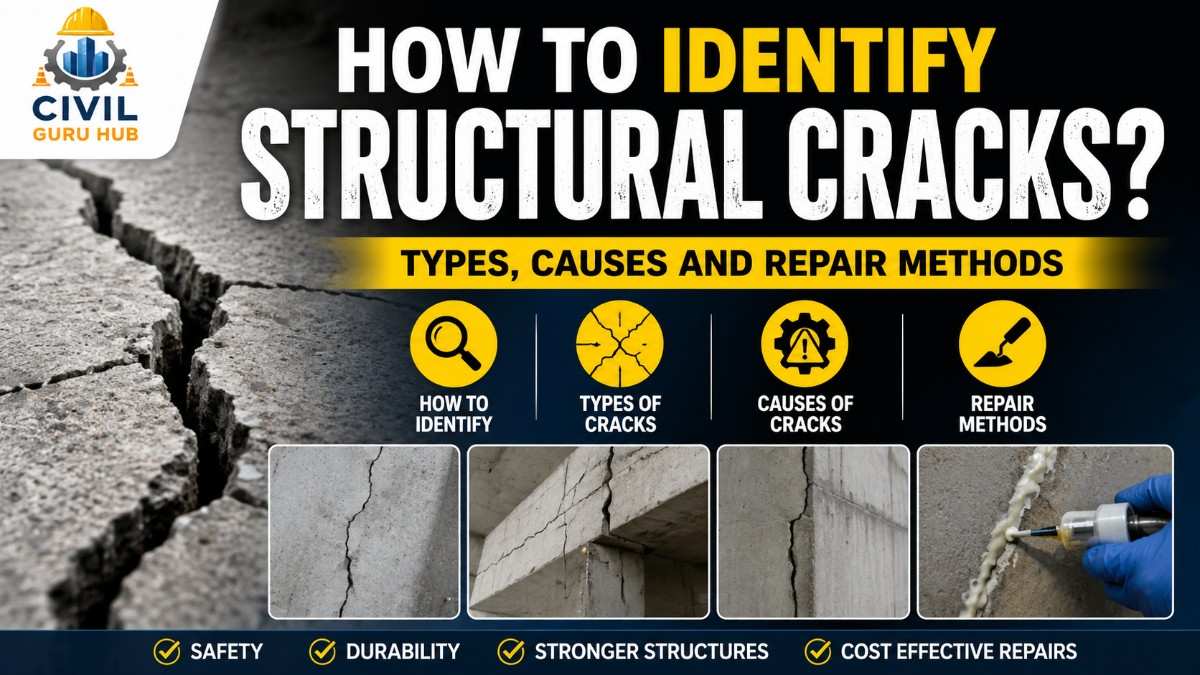
How to Identify Structural Cracks? Types, Causes, and Repair Methods
If structural cracks appear in a building, bridge, retaining wall, water tank, or any RCC structure, they should never be dismissed as mere superficial cracks. Often, junior engineers on-site fail to distinguish between plaster cracks and actual structural cracks. Consequently, a minor issue can gradually escalate into a serious structural failure.
An experienced civil engineer does not judge a crack solely by its width. They examine the crack’s location, direction, depth, pattern, age, moisture conditions, reinforcement placement, loading history, and construction records. This comprehensive assessment determines whether the crack is merely a finishing defect or if it is compromising the structure’s load-bearing capacity.
With rapid urbanization in India, the number of high-rise buildings, metro projects, bridges, and industrial structures is increasing. Therefore, identifying structural cracks has become a mandatory—not just basic—skill for every site engineer, quality engineer, structural engineer, and project manager.
In this article, we will go beyond theory. Drawing on practical site experience, we will understand:
- What structural cracks are.
- How to identify them on-site.
- Which cracks are dangerous.
- At what crack width an investigation becomes necessary.
- Which Indian and International standards govern this topic.
The objective of this guide is not merely to help you pass an exam, but to teach you to think like a practical site engineer.
What Are Structural Cracks?
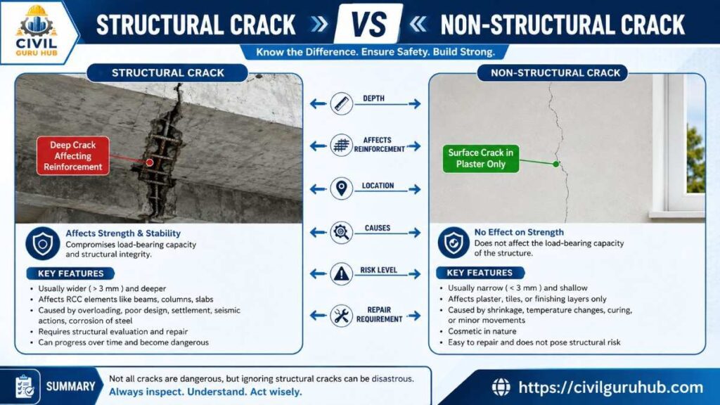
Simply put, structural cracks are those that directly or indirectly affect a structure’s strength, stability, or load-bearing capacity. These cracks generally do not remain limited to the plaster; instead, they develop deep into the concrete and, in many cases, extend all the way to the reinforcement (steel bars).
A common misconception is that every large crack is structural and every hairline crack is harmless. The reality is quite different. Sometimes, a crack as narrow as 0.2 mm can be dangerous if it is located in the tension zone of a beam or has developed due to reinforcement corrosion. Conversely, some surface shrinkage cracks may appear large but are often limited only to the plaster layer.
Consider a practical example from a construction site. Suppose a diagonal crack appears on the bottom face of a first-floor beam in a G+4 residential building. If an inspection reveals that the crack extends across both sides of the beam and widens as the load increases, it is a clear indication that the beam is struggling with shear stress or overloading. Covering such a crack with merely cosmetic repairs would be an engineering error.
Similarly, if a vertical crack develops parallel to the reinforcement in a column and rust stains are visible nearby, it could indicate reinforcement corrosion. Corrosion increases the volume of the steel, generating internal pressure within the concrete and leading to the formation of structural cracks.
An experienced engineer does not view a crack in isolation. They evaluate surrounding structural members, loading patterns, settlement history, and environmental exposure. It is through this holistic approach that the true severity of the crack can be understood.
Difference Between Structural and Non-Structural Cracks
This is the topic that causes the most confusion on-site. Often, a building owner panics when a crack is merely in the plaster. Conversely, dangerous cracks are sometimes dismissed as simple “plaster cracks.” Both situations pose risks to the project.
Non-structural cracks generally develop due to shrinkage, temperature variations, plaster drying, minor settlement, or finishing defects. They are not directly related to the structure’s load-bearing capacity. These cracks mostly occur at the surface level and do not immediately affect the structure’s stability.
In contrast, structural cracks can disrupt the load-transfer mechanism. They develop due to foundation settlement, overloading, poor detailing, reinforcement corrosion, inadequate design, seismic effects, or construction defects. If not repaired in time, the crack can gradually propagate, potentially compromising both the durability and safety of the structure.
Consider a practical example:
If a random hairline crack appears on a plastered bedroom wall—limited to the paint layer and producing no hollow sound when tapped with a hammer—it is likely a plaster shrinkage crack.
However, if a diagonal crack develops at the beam-column junction, extends up to the slab, and shows signs of seepage during the rainy season, a structural investigation is mandatory.
Comparison Table
| Parameter | Structural Cracks | Non-Structural Cracks |
|---|---|---|
| Load-Bearing Capacity | Can be affected | Normally unaffected |
| Crack Depth | Extends into the concrete | Mostly surface level |
| Repair | Structural repair required | Cosmetic repair suffices |
| Risk Level | Can be high | Low |
| Investigation | Mandatory | Situation-dependent |
| Future Growth | Can propagate | Often remains stable |
The most important takeaway for a field engineer is that no crack should be classified as merely cosmetic or structural without a proper inspection.
How to Identify Structural Cracks on Site?
Merely spotting a crack with the naked eye does not constitute an inspection. A professional crack investigation is a systematic process carried out by an experienced structural engineer.
First, the exact location of the crack is noted. Is the crack in a beam, slab, column, foundation wall, or retaining wall? The location itself provides an initial clue regarding the possible cause.
Next, the direction of the crack is observed. Vertical, horizontal, diagonal, map, or stepped cracks indicate different engineering issues. For instance, a diagonal crack in a beam might indicate shear failure, whereas a stepped crack in a masonry wall could indicate differential settlement.
The next step is measuring the crack width. Professional inspections utilize tools like crack width gauges or crack microscopes; relying on mere estimation is not an acceptable practice.
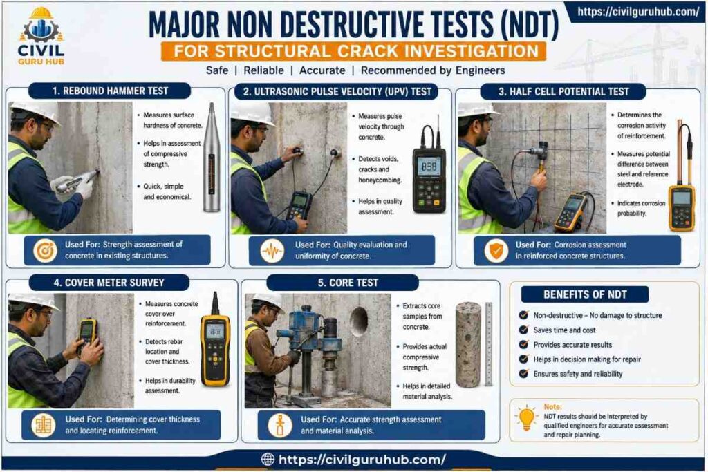
Subsequently, the crack depth is checked. There is a significant difference between a surface crack and a through-crack. If necessary, Non-Destructive Tests (NDT)—such as Ultrasonic Pulse Velocity (UPV), Rebound Hammer, Half-Cell Potential Test, or Core Test—are performed.
During the inspection, the engineer also observes whether the crack is active or dormant. A crack monitoring gauge may be installed for this purpose. If the crack width increases over a period of weeks or months, it is considered an active crack, necessitating a detailed investigation.
A competent site engineer maintains a photographic record, along with the date, dimensions, and location drawings, for every crack. This documentation is known as “Crack Mapping” and proves highly useful for future comparisons and repair planning.
Major Types of Structural Cracks
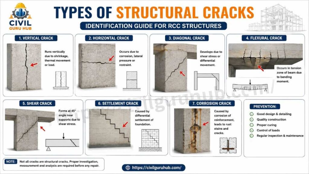
Not all cracks are alike. The pattern of a crack provides the most significant clue to understanding its cause.
Vertical Cracks
Vertical cracks can often be attributed to settlement, shrinkage, or reinforcement corrosion. If these appear in columns, a detailed investigation is essential.
Horizontal Cracks
Horizontal cracks generally develop in retaining walls or basement walls, or due to reinforcement corrosion. A horizontal crack in a column can be a serious warning sign.
Diagonal Cracks
Diagonal cracks near the beam-column junction are considered quite dangerous. They may indicate shear stress, earthquake loading, or differential settlement.
Flexural Cracks
Vertical cracks appearing on the bottom face of a beam near the mid-span are caused by flexural loading. They provide an indication for evaluating reinforcement detailing and load distribution.
Shear Cracks
These develop near the supports at an angle of approximately 45° and are related to the beam’s shear resistance.
Settlement Cracks
Stepped or diagonal crack patterns develop in masonry walls due to unequal foundation settlement.
Corrosion Cracks
When reinforcement rusts, the steel expands, causing longitudinal cracks to develop in the concrete cover. Rust stains are a common sign of this.
Crack Width Classification (Practical Engineering Approach)
Merely observing the crack is not enough; measuring its width is a crucial part of the engineering decision-making process.
| Crack Width | Practical Observation |
|---|---|
| < 0.1 mm | Hairline crack; monitoring recommended |
| 0.1–0.3 mm | Detailed inspection advisable |
| 0.3–0.5 mm | Repair planning required, depending on location |
| 0.5 mm | Structural assessment strongly recommended |
| 1 mm | Immediate engineering investigation required |
Keep in mind that the final decision is not based solely on width; the location and cause of the crack are even more important.
Important Standards Related to Structural Cracks
There are several standards available in India and at international level for structural cracks assessment and repair. Every Site Engineer should at least have a basic understanding of these documents.
Indian Standards
- IS 456:2000 – Plain and Reinforced Concrete Code of Practice (serviceability, durability and crack control provisions)
- IS 875 (Part 1–5) – Design Loads for Buildings and Structures
- IS 1893 (Part 1) – Criteria for Earthquake Resistant Design of Structures
- IS 13920 – Ductile Detailing of Reinforced Concrete Structures
- NBC 2016 (National Building Code of India) – Structural safety, inspection and maintenance guidelines
International References
- ACI 224R – Control of Cracking in Concrete Structures
- ACI 224.1R – Causes, Evaluation and Repair of Cracks
- ACI 562 – Assessment, Repair and Rehabilitation of Existing Concrete Structures
- ASTM C597 – Ultrasonic Pulse Velocity Test
- ASTM C805 – Rebound Hammer Test
These standards define the cause, evaluation, inspection and repair methodology of cracks on a scientific basis. In a practical project the engineer should take reference of these standards along with the project specifications and the consultant’s requirements.
What Causes Structural Cracks?
Many new site engineers believe that structural cracks are caused solely by poor-quality concrete. However, in practical projects, this is not entirely accurate. A single crack can stem from multiple interconnected reasons. Sometimes the design is sound but the construction is flawed; at other times, the construction is excellent but the foundation is weak; and frequently, environmental factors and maintenance issues play a significant role in the development of cracks.
An experienced civil engineer does not suggest repairs the moment a crack is spotted. Instead, they first conduct a root-cause analysis. If a crack is simply filled with putty or mortar without understanding the underlying cause, it is likely to reappear after a few months. That is why a well-known engineering principle is followed:
“Repair the Cause First, Then Repair the Crack.”
During the site investigation, the engineer should examine the structure’s age, loading history, soil investigation report, reinforcement detailing, concrete grade, exposure to weather conditions, and maintenance records. Collectively, this information helps in identifying the actual cause of the crack.
The major causes listed below are commonly observed in almost all RCC and masonry structures.
Foundation Settlement – The Most Common Cause of Structural Cracks
The foundation is the backbone of any structure. If the foundation settles uniformly, there are generally no major issues. However, when settlement occurs unevenly across different parts of the building, internal stresses develop within the structure, and structural cracks gradually begin to appear.
This phenomenon is known as Differential Settlement.
Consider a practical example: a G+3 residential building constructed on soft clay soil. If proper soil investigation was not conducted and the foundation depth was insufficient, one corner of the building might settle more than another after a few years. In such a scenario, diagonal or stepped cracks may start appearing in the masonry walls. If the settlement continues, beams and slabs may also come under stress and develop cracks.
Common causes of foundation settlement include poor soil bearing capacity, inadequate compaction, nearby excavation, fluctuations in the groundwater level, leaking underground pipelines, and vibrations from heavy traffic.
During a site inspection, an engineer should not look merely at the cracks. They should also observe whether:
- Doors and windows are jamming.
- There is uneven settlement in the flooring.
- There are variations in the plinth level.
- The boundary wall is also showing cracks.
These indirect indicators help confirm the presence of foundation problems.
Reinforcement Corrosion – The Silent Killer Weakening the Structure from Within
Concrete is considered a durable material, but when the reinforcement within it succumbs to corrosion, the structure’s lifespan can be significantly reduced. Structural cracks resulting from corrosion may appear very fine initially, but over time, they can break through the concrete cover and lead to spalling.
When steel rusts, its volume expands to many times that of the original steel. This expansion exerts pressure on the surrounding concrete, causing longitudinal cracks to develop parallel to the reinforcement. If corrosion persists, the concrete cover begins to detach, exposing the reinforcement.
The risk of corrosion is heightened in coastal areas, industrial zones, and chloride-rich environments; consequently, concrete cover thickness and concrete quality become crucial factors.
Practical signs on-site that help identify corrosion include:
- Brown or reddish rust stains near cracks.
- Breaking or spalling of the concrete cover.
- Exposure of the reinforcement.
- A hollow sound when tapped with a hammer.
- Presence of dampness and seepage.
Engineers also employ Non-Destructive Testing (NDT) methods—such as the Half-Cell Potential Test, Cover Meter Survey, and Carbonation Test—to assess corrosion. If corrosion is extensive, simple crack filling is insufficient; reinforcement treatment and structural repairs become necessary.
Overloading and Change of Building Usage
Every structure is designed with specific loading conditions in mind. When the actual load exceeds the design load, additional stress develops within the structural members, eventually leading to the appearance of structural cracks.
Consider a scenario where a residential building is converted into a warehouse without a structural assessment. Residential floors are typically designed for relatively lower live loads, whereas warehouses involve the stacking of heavy materials. Continuous excessive loading on beams and slabs can lead to the development of flexural and shear cracks.
Similarly, installing heavy water tanks, telecom towers, solar panel structures, or adding extra floors on the rooftop without a structural redesign can also be dangerous.
During an inspection, the engineer should also obtain the following information from the building owner:
- What was the building’s original purpose?
- For what purpose is it currently being used?
- Have there been any recent renovations or additional construction?
- Has any heavy machinery been installed?
Often, the actual cause of cracking is not the quality of the concrete, but rather unauthorized loading.
To read more articles, check the following guides:
What Are the Types of Foundations? A Complete Guide to Shallow and Deep Foundation 2026
BBS in Construction:A full guide for Calculation, Formula & Examples
What Are the 12 Types of Drain? A Complete Guide
Design Errors and Poor Structural Detailing
If there are deficiencies in the structural design itself, even the highest quality construction cannot guarantee long-term performance. Errors made during the design stage may manifest as structural cracks years later.
Common design-related mistakes include inadequate reinforcement, incorrect load calculations, insufficient development length, poor anchorage detailing, and improper detailing at beam-column junctions.
Failure to adhere to ductile detailing practices in earthquake-prone areas can also become a major issue. Therefore, the proper implementation of the provisions outlined in IS 13920 and IS 1893 is crucial.
In one practical project, a consultant failed to provide additional reinforcement around a slab opening. Although the construction quality was good, cracks developed at the corners of the opening during the service period due to stress concentration. An investigation revealed that the issue stemmed from a detailing deficiency rather than poor workmanship.
Consequently, verifying structural drawings and the Bar Bending Schedule (BBS) is essential when investigating cracks.
Construction Defects – Minor Execution Errors, Major Consequences
Small errors made during execution at the site can lead to significant structural cracks later on. Often, the design is flawless, but the structure fails to perform as expected due to poor workmanship.
Improper vibration during concrete placement can result in honeycombing. Inadequate curing can lead to the formation of plastic shrinkage and drying shrinkage cracks. Failure to use cover blocks during reinforcement placement also increases the risk of corrosion.
Cold joints are another common construction defect. Bonding can be compromised when concrete placement is not continuous and the next layer is cast without proper surface preparation.
Quality Engineers should pay special attention to the following points during casting:
- The concrete slump must be within specifications.
- Proper compaction must be ensured.
- The required curing period must be maintained.
- Reinforcement must be placed according to the drawings.
- Cover blocks must be of the approved size.
- Formwork must be leak-proof.
Effective quality control practices can significantly reduce the likelihood of future cracking.
See the below video regarding Slump test and Types of Cement
Earthquakes, Temperature Variations, and Environmental Effects
Natural forces are also significant causes of structural cracks. During an earthquake, cyclic loading develops within the structure, creating additional stress on beam-column joints, shear walls, and masonry infill.
Post-earthquake, diagonal cracks, X-shaped cracks, or cracks at beam-column junctions require special attention.
Temperature variation is another factor that is often overlooked. Concrete undergoes continuous expansion and contraction; if expansion joints are not properly provided or if movement is restrained, thermal stresses develop.
Water ingress is also a major cause of long-term damage. Continuous seepage accelerates reinforcement corrosion, and in freeze-thaw regions, it can further hasten concrete deterioration and crack propagation.
A crack repair design is not considered complete without evaluating environmental exposure.
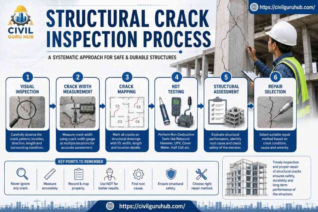
Professional Procedure for Structural Cracks Inspection
A professional engineer never forms a final opinion based solely on a visual assessment. Crack investigation is a systematic engineering process.
The process begins with a visual inspection to observe the crack’s location, direction, continuity, and the surrounding conditions. Subsequently, the crack width is measured using a crack width gauge.
In the next stage, the crack’s length and depth are recorded. Each crack is assigned a unique identification number, and its exact position is marked on the structure’s layout drawing.
If a crack appears to be active, a crack monitor or tell-tale gauge is installed to observe any movement over a period of weeks or months.
If necessary, Non-Destructive Testing (NDT) methods are performed:
| Test | Purpose |
|---|---|
| Rebound Hammer Test (ASTM C805) | To assess surface hardness |
| Ultrasonic Pulse Velocity – UPV (ASTM C597) | To evaluate internal concrete quality |
| Half-Cell Potential Test | To assess the probability of reinforcement corrosion |
| Cover Meter Survey | To identify concrete cover and reinforcement location |
| Core Test | To verify concrete compressive strength |
These tests help the engineer understand the actual structural condition underlying the crack.
Crack Mapping – A Skill Every Site Engineer Should Possess
Crack mapping is a crucial process in professional structural assessment. Its objective goes beyond merely photographing the crack; it involves maintaining a comprehensive engineering record.
A crack map generally includes the following information:
| Observation | To be Recorded |
|---|---|
| Crack ID | Yes |
| Date of Inspection | Date |
| Member Type | Beam, Slab, Column, Wall |
| Crack Length | In mm or m |
| Crack Width | In mm |
| Crack Direction | Transverse, Longitudinal,Vertical, Horizontal, Diagonal |
| Moisture Presence | Yes / No |
| Rust Stains | Yes / No |
| Active or Dormant | Based on observation |
| Photograph | Mandatory |
Monitoring the same crack every 15 or 30 days makes it much easier to understand its growth trend. The urgency of repairs is determined based on this information.
Practical Calculation – Example of Crack Width Measurement
Suppose a crack is observed in a beam during inspection. A measurement is taken using a crack width gauge.
Observed Data:
Crack Length = 850 mm
Maximum Crack Width = 0.45 mm
Beam Location = Mid-span
Visible Rust = No
Crack Pattern = Vertical
Engineering Interpretation:
A crack with a width of 0.45 mm cannot be ignored based on width alone. Since the crack is located in the tension zone of the beam, a detailed structural assessment is advisable. If the crack width increases during monitoring, both load evaluation and repair planning will be required.
The final decision here will be based not just on the width, but on a combination of factors including the crack location, reinforcement condition, and loading history.
What Should Be Checked Before Repairing Structural Cracks?
A common mistake in many projects is simply filling a crack with cement mortar or putty as soon as it appears. While the crack may seem to disappear for a while, it often reappears after a few months. The reason is simple: crack repair and structural repair are two different things.
An experienced structural engineer always identifies the root cause of the crack before commencing repairs. If the foundation is still settling, reinforcement corrosion is ongoing, or a beam is overloaded, merely filling the crack will not solve the problem.
Before formulating a repair plan, the engineer needs answers to the following questions:
- Is the crack active or dormant?
- Is the crack superficial, or does it extend through the entire depth?
- Is the reinforcement in good condition, or is it corroded?
- Is the structural member load-bearing or non-load-bearing?
- Is the crack width stable, or is it increasing?
- Is there any water seepage?
- Is the structure currently in service, or can the load be temporarily removed?
This analysis forms the foundation for selecting the appropriate repair method.
Epoxy Injection – The Most Effective Repair Method for Fine Structural Cracks
Epoxy injection is considered the most widely accepted repair method when structural cracks are relatively narrow and the concrete on both sides of the crack remains structurally sound.
The process begins by cleaning the crack. Injection ports are fixed along the crack, and the surface is sealed with epoxy paste. Subsequently, liquid epoxy resin is injected into the crack using either a low-pressure or high-pressure system. The epoxy penetrates the full depth of the crack and, upon hardening, rebonds the concrete.
Consider a practical site example: a 0.25 mm flexural crack has developed in the RCC beam of an office building. Investigation reveals that the crack is stable, the reinforcement is not corroded, and the beam’s load-carrying capacity has not been compromised. In such a scenario, epoxy injection can be an economical and durable solution.
However, it is important to note that if the crack is subject to active movement or if settlement is ongoing, epoxy injection may fail. Therefore, controlling the crack movement is essential before proceeding.
Routing and Sealing – A Practical Solution for Surface Cracks
Not every crack is structural; often, surface cracks merely serve as pathways for water ingress. In such cases, routing and sealing is an effective repair technique.
This method involves enlarging the crack into a V-shaped or U-shaped groove. After cleaning the groove, it is filled with a suitable sealant or repair material. The primary objective is to block water entry and prevent further deterioration.
This method is generally suitable for non-moving surface cracks. If the crack is a deep structural one within a load-bearing member, routing and sealing alone is insufficient.
Site engineers should consider the crack’s location and environmental exposure when selecting materials. Waterproof sealants are preferred for exterior walls, water-retaining structures, and basement walls.
Grouting and Crack Filling
Grouting is employed when internal voids or honeycombing accompany the cracks. Cementitious or chemical grout is injected under pressure into the cracks and the surrounding voids.
Grouting is a widely used repair technique for foundation structures, retaining walls, and mass concrete members.
In one practical instance, multiple cracks and seepage appeared in a basement retaining wall. Investigation revealed that water pressure was continuously acting upon the wall. Simply filling the cracks would not have resolved the issue. Pressure grouting was followed by waterproofing treatment and drainage improvements. This integrated approach provided a long-term solution.
Controlling injection pressure is crucial during the grouting process. Excessive pressure can lead to the formation of new cracks.
Stitching Method – When Mechanical Strength Needs to be Provided to the Crack
If a crack is relatively stable but requires additional mechanical support across it, the crack stitching method can be employed.
In this method, slots are cut across the crack, and U-shaped steel bars—or “stitching dogs”—are installed. Subsequently, the slots are filled with high-strength grout or epoxy mortar.
This technique is useful for cracks where movement has ceased and additional continuity needs to be restored to the structural member.
However, it is essential to eliminate the root cause of the crack before stitching. If settlement is ongoing, even a stitched crack may reopen in the future.
RCC Jacketing – A Proven Method to Strengthen Weak Structural Members
RCC jacketing is a widely adopted strengthening method used when the strength of a beam, column, or footing is significantly reduced or when it needs to support additional loads.
In this process, a new layer of concrete is cast around the existing structural member after providing additional reinforcement. This increases both the member’s cross-section and its load-bearing capacity.
For example, suppose an additional floor is to be constructed atop an existing commercial building. A structural audit reveals that the existing columns are inadequate to support the additional load. In such a scenario, a consultant might recommend RCC jacketing.
Establishing a proper bond between the old and new concrete is crucial during the jacketing process. Techniques such as surface roughening and the use of bonding agents and shear connectors are employed in accordance with project specifications.
FRP Wrapping and Steel Plate Bonding
The use of Fiber Reinforced Polymer (FRP) wrapping is rapidly increasing in modern rehabilitation projects. Carbon Fiber Reinforced Polymer (CFRP) and Glass Fiber Reinforced Polymer (GFRP) sheets are bonded to structural members using epoxy adhesive.
The major advantages of FRP are:
- Lightweight
- High tensile strength
- Fast installation
- Corrosion resistance
Its use has become quite common in bridges, industrial buildings, and seismic retrofitting projects.
On the other hand, the steel plate bonding technique involves fixing steel plates to the damaged member using epoxy and anchor bolts. While this method is also effective for strengthening, it requires more corrosion protection and maintenance compared to FRP.
The final choice of method should be based on structural design calculations and the recommendations of consultants.
To read more articles, check the following guides:
What Are the Types of Wearing Coat in Bridges? 10 Easy Explanations
What Are Toe Wall and Breast Wall? Complete Comparison in 12 Points
How Do Engineers Predict Box Culvert Failure? 7 proven Factors That Civil Engineer Must Know
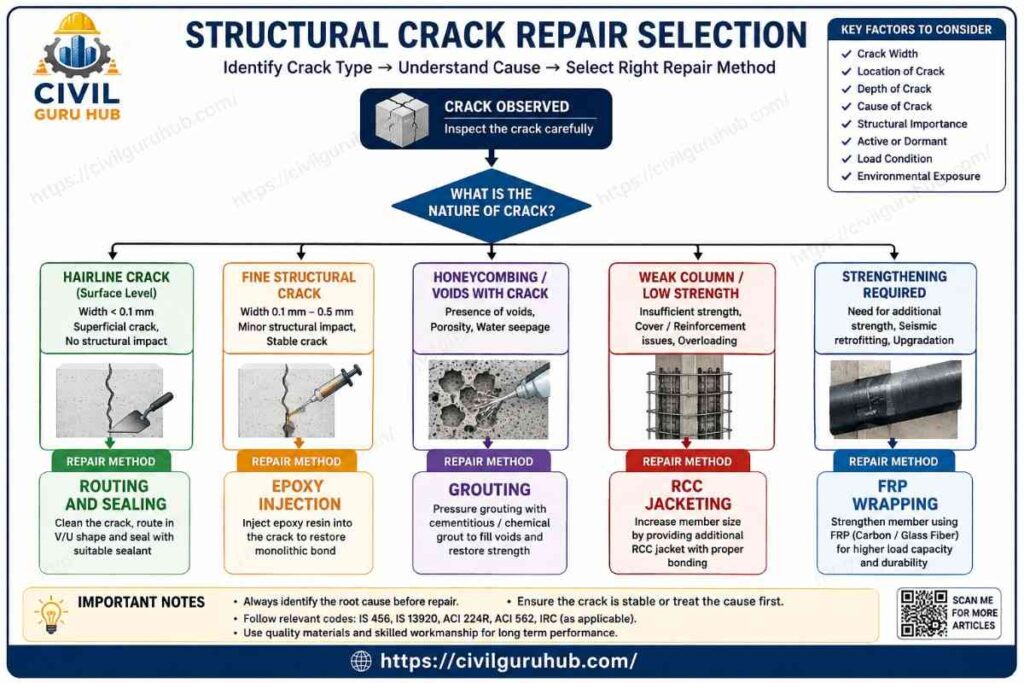
Repair Method Selection Comparison Table
| Crack Condition | Recommended Repair |
|---|---|
| Hairline Stable Crack | Routing & Sealing |
| Fine Structural Crack | Epoxy Injection |
| Honeycombing + Cracks | Pressure Grouting |
| Stable Wide Crack | Stitching |
| Weak Beam/Column | RCC Jacketing |
| Strengthening Required | FRP Wrapping |
| Strengthening Required | Steel Plate Bonding |
Note: Final repair method should always be decided after detailed structural assessment.
Common Mistakes in Addressing Structural Cracks
In practical projects, repair failures are often caused by engineering errors rather than the materials themselves.
The most common mistake is covering the crack with plaster without investigating it first. While this provides the owner with temporary satisfaction, the underlying structural problem remains hidden.
Another major mistake is ignoring the source of moisture. If seepage persists, the repair material can deteriorate prematurely.
In many projects, crack width is merely estimated rather than measured; a crack width gauge should be used during professional inspections.
Another common error is failing to monitor the repair. Periodic inspections remain necessary even after an active crack has been repaired.
Expert Tips – Based on Over 11 Years of Practical Site Experience
An experienced Civil Engineer looks beyond the crack itself to the engineering story hidden behind it. If you are a Site Engineer, always keep these practical tips in mind:
- Never declare a crack harmless just by looking at it.
- Prioritize the inspection of cracks at beam-column junctions.
- Never ignore rust stains.
- Always create a crack map before undertaking repairs.
- Maintain a photographic record of crack widths.
- Monitor the same crack at regular intervals.
- Observe the building’s exterior for signs of foundation settlement.
- When in doubt, seeking the opinion of a Structural Engineer is always the best option.
Civil Engineering Interview Questions
Q1. What is the main difference between a structural cracks and a non-structural cracks?
A structural cracks can affect load-carrying capacity, whereas a non-structural cracks is generally just an issue related to finishing or durability.
Q2. What type of failure can a diagonal crack in a beam indicate?
It can generally indicate shear stress or shear failure.
Q3. What is the first visible sign of reinforcement corrosion?
Rust stains and longitudinal cracks running parallel to the reinforcement.
Q4. What is crack mapping?
The systematic documentation of all cracks in a structure.
Q5. When is epoxy injection used?
For stable and fine structural cracks.
Conclusion
Structural cracks can serve as a warning signal for any RCC or masonry structure. however, not every crack indicates structural failure. The role of a professional Civil Engineer extends beyond merely observing the crack; it involves understanding the underlying engineering causes. Permanent repair is impossible without identifying factors such as foundation settlement, reinforcement corrosion, overloading, design deficiencies, and poor workmanship.
A practical engineering approach dictates: “Eliminate the cause, then repair the crack.” Adhering to this principle is essential for enhancing a building’s durability, safety, and service life. Regular inspections, crack mapping, proper documentation, and the implementation of relevant standards (such as IS 456, IS 1893, IS 13920, NBC 2016, and ACI 224R) should be integral components of any structural maintenance program.
For Junior Site Engineers, QA/QC Engineers, Structural Engineers, or Civil Engineering students, the ability to correctly identify structural cracks and understand repair techniques will prove invaluable in making practical decisions on-site. An accurate diagnosis is the first and most critical step toward a successful repair.
About the Author
My name is Susanta Kumar Mohapatra. I am a Civil Engineering professional with over 11 years of practical experience in the construction and infrastructure sectors. I hold a B.Tech degree in Civil Engineering and an M.E. degree in Construction Management. Throughout my professional career, I have worked in key areas such as road construction, bridge projects, quality control, material testing, concrete mix design, highway engineering, quantity estimation, project planning, site execution, and construction management.
I launched CivilGuruHub.com with the aim of sharing my passion for Civil Engineering and my practical knowledge with a wider audience. The primary objective of this website is to provide practical, industry-oriented information in simple language to Civil Engineering students, site engineers, quality engineers, quantity surveyors, contractors, and construction professionals. Here, I publish detailed, original, and research-based articles on topics such as construction technology, concrete technology, highway engineering, structural engineering, material testing, IS codes, IRC codes, quantity surveying, estimation and costing, project management, tendering, and Civil Engineering calculators.
Alongside the website, I also run a YouTube channel named “The Civil Site,” where I explain practical site experiences, laboratory tests, construction techniques, engineering calculations, software tutorials, and technical concepts through easy-to-understand videos. My goal is to ensure that every student and engineer understands not just the theory, but also its practical application.
Additionally, I share educational content related to general knowledge, quizzes, and competitive exam preparation through my YouTube channel, “Daily IQ Hub.” The aim of this channel is to enhance viewers’ knowledge and strengthen their exam preparation.
I believe that a successful engineer is one who is always ready to learn and continuously updates their practical knowledge. With this mindset, I always strive to provide high-quality, reliable, practical, and industry-standard content through CivilGuruHub.com and my YouTube channels, enabling every reader and viewer to excel in their careers.
Thank you sincerely for your trust and support. I am confident that CivilGuruHub.com and my educational platforms will prove to be reliable companions in your learning journey and professional growth. If you wish to take your knowledge in the field of Civil Engineering to the next level, please continue to follow our articles and videos regularly. We will keep bringing you fresh, practical, and industry-focused content.
Frequently Asked Questions (Structural Cracks)
Is every structural cracks dangerous?
No. A structural assessment of every crack is necessary. Its location, width, and cause determine how serious the crack is.
At what width does a crack become a cause for concern?
The decision isn’t based on width alone. However, cracks wider than approximately 0.3 mm may require an engineering evaluation.
Can structural cracks close on their own?
Normally, no. If the root cause remains active, the crack may widen further.
Does painting permanently repair a crack?
No. Paint merely hides the crack.
Is there a link between seepage and cracks?
Yes. Water ingress accelerates the corrosion of reinforcement bars.
At what intervals should crack monitors be checked?
Monitoring can be done weekly or monthly, depending on project conditions.
Can RCC jacketing extend a building’s lifespan?
If executed with proper design and workmanship, it is an effective method for structural strengthening.
Should every building be inspected after an earthquake?
It is advisable to conduct visual and structural inspections following a significant earthquake.
Can foundation settlement be repaired?
Once the cause is identified, techniques such as underpinning or other foundation improvement methods can be considered.
Is monitoring necessary after crack repair?
Absolutely. It confirms whether the repair was successful.

[106678]supplies professional anti-violence equipments and solutions for the whole world with strong and perfect production capacity. anti-violence.org