
Introduction
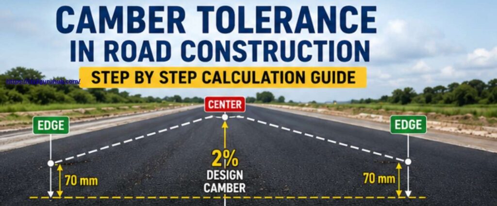
In the road construction industry, the role of camber plays a crucial part in maintaining effective surface drainage and ensuring optimal pavement performance. In any highway, village road, city road, or rigid pavement project, if proper camber is not provided, rainwater begins to stagnate on the road surface.
This water stagnation causes the pavement to weaken, gradually leading to the development of defects such as cracks, potholes, rutting, and edge failures. For this very reason, in highway engineering, experts regard camber not merely as a simple slope but as a critical factor determining pavement safety and durability.
Generally, engineers provide road camber sloping from the centerline towards the edges to facilitate the easy flow of rainwater into side drains or onto the shoulders. However, simply providing camber in accordance with the design specifications is not sufficient at the construction site.
It is also essential to verify the extent of the allowable variation between the actual constructed surface and the designed camber. This permissible variation is referred to as “Camber Tolerance.” The specifications laid out by the IRC (Indian Roads Congress) and MoRTH (Ministry of Road Transport and Highways) clearly define the permissible tolerance limits for various pavement layers; adherence to these limits is mandatory for effective quality control.
In modern highway projects, advanced instruments—such as Total Stations, Auto Levels, paver sensors, and string line systems—are widely utilized; nevertheless, site engineers and quality engineers must still possess a thorough understanding of manual camber calculation and tolerance verification methods.
Under practical site conditions, the actual camber frequently deviates from the designed value due to factors such as instrument errors, improper compaction (rolling), paver mismatches, or variations in layer thickness. If engineers do not conduct tolerance checks in a timely manner, the risk of future pavement failure can increase significantly.
In this article, through a step-by-step approach utilizing practical examples, formulas, IRC standards, and site calculation methods, we will gain a detailed understanding of how Camber Tolerance is calculated in road construction and how it is verified in the field.
What is Camber? Its Importance in Road Construction
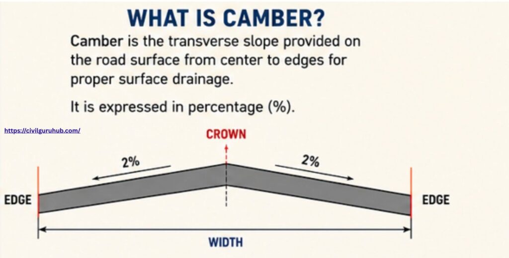
In highway engineering, engineers implement camber as a crucial feature in the form of a transverse slope on the road surface. This slope descends from the center towards both edges of the road, facilitating the easy drainage of rainwater and preventing water from accumulating on the surface. If a road lacks proper camber, water stagnation causes the pavement to deteriorate rapidly. For this reason, modern highway design treats camber tolerance with great seriousness.
Engineers provide a camber of generally 2% to 3% for flexible pavement roads, whereas they design rigid or cement concrete pavements with a comparatively flatter slope. Engineers maintain an appropriate camber tolerance in every project, as both excessive and insufficient slopes can negatively impact driving comfort and the drainage system.
The selection of camber primarily depends on rainfall intensity, the type of pavement material used, and the road’s classification. In regions that experience high rainfall, engineers adopt a slightly higher camber tolerance to ensure the rapid runoff of water. During the construction phase, highway engineers ensure that precise measurements and rigorous quality checks maintain the required camber tolerance.
Engineers typically express camber as a percentage. For instance, if the vertical difference between the road’s center and its edge is 70 mm, and the half-width of the carriageway is 3.5 meters, the camber would be approximately 2%. Engineers utilize a standard formula for this calculation:
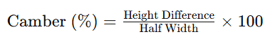
Here, “Height Difference” refers to the difference in elevation between the center and the edge, while “Half Width” represents half the width of the carriageway. Proper camber tolerance enhances the road’s durability, safety, and drainage efficiency. Therefore, maintaining accurate camber tolerance is considered crucial in both highway construction and maintenance.
What is Camber Tolerance?
In road construction and highway engineering, camber tolerance is considered a crucial quality control parameter. Camber refers to the slope provided on the road surface, designed to facilitate the drainage of rainwater toward the sides of the road. However, during the construction phase, achieving the exact designed slope is not always practically feasible. For this reason, permissible limits for camber tolerance are defined within established standards and specifications.
Simply put, camber tolerance signifies the allowable variation relative to the designed camber. For instance, if a road is designed with a camber of 2% and the specifications permit a variation of ±0.17%, the actual camber may range between 1.83% and 2.17% while still being considered acceptable. These limits are generally determined in accordance with guidelines issued by the IRC (Indian Roads Congress) and MoRTH (Ministry of Road Transport and Highways).
The specific value of camber tolerance may vary depending on the type of pavement, surface layers, and construction methods employed. The allowable variation differs for flexible pavements, rigid pavements, and roads with granular surfaces. Consequently, site engineers are required to utilize appropriate checking and leveling instruments during the construction process.
If the camber tolerance deviates beyond the specified limits, the overall performance of the road is directly compromised. The immediate impact is on water drainage, leading to water stagnation on the road surface. Furthermore, riding comfort is diminished, and the risk of pavement failures—such as cracks, potholes, and surface deformation—increases significantly. In many instances, excessive deviation necessitates rectification work by the contractor, who may also face financial penalties in the form of payment deductions.
For these reasons, camber tolerance is subject to regular monitoring throughout highway construction projects. Maintaining proper camber tolerance is absolutely essential for ensuring the construction of durable, safe, and long-lasting roads.
The Importance of Camber Tolerance in Road Construction: IRC and MoRTH Standards
In India, highway and road construction works follow standards established by the Indian Roads Congress (IRC) and the Ministry of Road Transport and Highways (MoRTH). Maintaining the correct camber tolerance is considered absolutely essential for enhancing road quality, safety, and drainage efficiency. If the road’s camber falls outside the prescribed limits, rainwater begins to accumulate on the road surface, thereby exacerbating issues such as cracking, potholes, and general road damage.
In road construction, camber tolerance ensures that the road surface adheres strictly to the specified gradient (slope). In India, the MoRTH Specifications for Road and Bridge Works and IRC guidelines stipulate the permissible tolerances for the various layers of a road structure. These standards define the extent of level variation that is deemed acceptable during the construction process.
Specifically, IRC:73 (Geometric Design Standards) and IRC:SP:84 (Highway Construction Guidelines) provide detailed information regarding the geometric accuracy and drainage requirements pertinent to road construction. Maintaining the correct camber tolerance not only improves the riding quality of the road but also extends the overall lifespan of the pavement.
MoRTH Surface Level Tolerances
| Layer | Permissible Tolerance |
|---|---|
| Subgrade | ±20 mm |
| GSB | ±10 mm |
| DLC | ±6 mm |
| PQC | ±5 mm |
The tolerances listed above directly influence the camber tolerance, as any variation in the surface level inevitably alters the camber value. Consequently, in highway projects, regular level checks and the use of precision survey instruments are employed to ensure that the camber tolerance remains strictly within the prescribed limits.
Maintaining the correct camber tolerance is considered a critical component of any highway construction project, as it is fundamental to ensuring effective road drainage, a smooth riding surface, and a durable, long-lasting pavement structure.
Basic Principles of Road Camber Calculation
Camber tolerance plays a crucial role in road construction and quality control. Whenever a road surface is prepared, it is essential to provide a proper slope so that rainwater can drain easily towards the sides of the road. This slope is referred to as “camber.” If the correct camber tolerance is not maintained on a road, problems such as waterlogging, potholes, and surface damage begin to develop very rapidly.
To calculate a road’s camber, the vertical difference between the road’s center level and its edge level is measured first. This difference is calculated as a percentage relative to the road’s width. Maintaining proper camber tolerance is essential for both highway safety and the longevity of the pavement.
If the carriageway width is 3500 mm and the designed camber is specified as 2%, a standard formula is used to determine the required level difference:
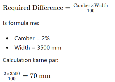
This means that a total level difference of 70 mm is required between the center and the edge of the road. This value ensures that water drains smoothly off the road surface rather than pooling on it. At construction sites, engineers and survey teams conduct regular checks to ensure that the specified camber tolerance is achieved.
If the actual level difference deviates—either exceeding or falling short of the design value, the camber tolerance is considered to have failed. This adversely affects both riding comfort and pavement durability. Therefore, maintaining camber tolerance through precise measurements, leveling instruments, and regular inspections constitutes an essential part of road quality control. Accurate camber tolerance serves as the very foundation for the construction of long-lasting and safe roadways.
Step-by-Step Camber Tolerance Calculation
Now, we will understand the actual practical site methods used in highway projects.
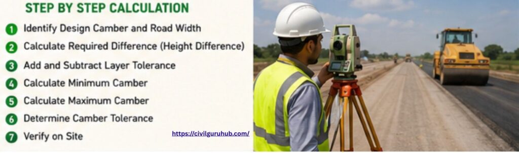
Step 1 – Identifying the Design Camber
Camber tolerance is one of the most critical quality parameters in road construction. If the correct design camber is not identified right at the outset, the entire pavement drainage system could be compromised later on. Therefore, the engineer must first verify the exact camber value by cross-referencing the approved drawings, General Arrangement Drawings (GADs), and cross-section drawings. Generally, distinct design slopes are specified for each layer—such as PQC, DLC, WMM, or bituminous layers. Before commencing work on-site, it is imperative to utilize the latest revision of the drawings approved by the design team; using outdated drawings can lead to a camber mismatch, thereby increasing the risk of rejection at later stages.
For instance, if the specified design camber for a PQC layer is 2% and the carriageway width is 3500 mm, the engineer must conduct field checks strictly in accordance with these values. This base value subsequently serves as the foundation for calculating camber tolerance. Frequently, contractors and survey teams on-site inadvertently use outdated drawings, resulting in a discrepancy between the actual constructed slope and the approved design slope. Consequently, the Quality Engineer must verify during every shift that the ongoing execution strictly adheres to the approved “Issued for Construction” (IFC) drawings.
During the camber identification process, it is also essential to confirm the alignment of the centerline and edge lines, as well as the intended direction of drainage. If the slope is constructed in the opposite direction, it can lead to water stagnation. For this very reason, the initial step in verifying camber tolerance involves a thorough study of the drawings. Maintaining an acceptable camber tolerance is achievable only through proper identification. In every highway project, maintaining the correct camber tolerance is of paramount importance for ensuring both pavement performance and long-term durability. This specific step establishes the complete foundation for all subsequent on-site inspections and measurements; indeed, achieving proper camber tolerance is practically impossible without a precise understanding of the design specifications.
| Parameter | Value |
|---|---|
| Layer Type | PQC |
| Design Camber | 2% |
| Road Width | 3500 mm |
| Source of Data | Approved Cross Section |
| Verification Required | Latest Approved Drawing |
Step 2 – Calculating the Required Height Difference
Once the design camber has been identified, the next crucial step is to calculate the required height difference. This calculation determines the vertical level difference between the center and the edge of the road. The actual slope is constructed based on this specific value. In highway engineering, maintaining the correct camber tolerance plays a vital role in ensuring proper drainage. If the required height difference is not calculated accurately, the final pavement surface may suffer from uneven drainage.
Based on the following example:
Design Camber = 2%
Road Width = 3500 mm
Applying the formula:
Difference = (2 × 3500) / 100
Result:
70 mm
This implies that the center of the road should be 70 mm higher than the edge. This is a theoretical value that represents the ideal pavement condition. Site execution and finishing operations are carried out in accordance with this reference value. The survey team typically checks the Reduced Levels (RLs) using an auto level or a total station to ensure that the required height difference is being achieved.
This step is directly linked to camber tolerance, as the actual constructed slope is verified against this calculated difference. If the difference is insufficient, water will not flow properly toward the shoulders; conversely, if the difference is excessive, it may lead to riding discomfort. Therefore, an accurate calculation of the height difference is essential for maintaining proper camber tolerance.
In practical site conditions, variations may arise due to factors such as shuttering settlement, concrete vibration, and finishing errors. Consequently, the engineer must have a clear understanding of the theoretical difference to effectively compare it with actual field measurements. The calculation of the required height difference for each pavement layer serves as the fundamental basis for future verification of camber tolerance. Ultimately, an accurate level difference ensures acceptable camber tolerance and enhances the road’s drainage efficiency.
| Parameter | Value |
|---|---|
| Design Camber | 2% |
| Road Width | 3500 mm |
| Calculated Difference | 70 mm |
| Center Position | Higher |
| Edge Position | Lower |
Step 3 – Adding and Subtracting Layer Tolerance
In road construction, merely establishing a theoretical slope is not sufficient; permissible construction variations must also be taken into account. For this reason, layer tolerances are applied in accordance with MoRTH specifications. These tolerances are provided to accommodate practical errors inherent in the construction process. Once the theoretical height difference has been calculated, the acceptable construction range is derived by adding and subtracting the permissible tolerance from that value. This process constitutes the most critical stage in accurately determining the camber tolerance.
Based on the example:
Theoretical Difference = 70 mm
PQC Tolerance = ±5 mm
Therefore:
Minimum Difference = 70 − 5 = 65 mm
Maximum Difference = 70 + 5 = 75 mm
This implies that if the actual constructed level difference falls between 65 mm and 75 mm, the pavement is deemed acceptable. This specific range is utilized by the Quality Engineer during field inspections. In construction activities, factors such as shuttering movement, machine vibrations, and finishing variations are common occurrences; consequently, maintaining the exact theoretical value during practical execution is often difficult. It is for this very reason that permissible camber tolerances are allowed.
If the constructed difference falls below the minimum limit, water drainage may be compromised. Conversely, if the maximum limit is exceeded, the riding quality of the pavement may be adversely affected. In either scenario, the risk of rejection increases. Therefore, the engineer must conduct continuous level checks to ensure that the specified camber tolerance is consistently maintained.
The application of layer tolerance is an extremely vital process within quality control. It is through this specific step that the acceptable range for execution is defined. In highway projects, maintaining the approved camber tolerance is essential for ensuring both the durability and the service life of the pavement. The accurate application of tolerances serves to minimize future maintenance issues and enhance overall road performance.
| Parameter | Value |
|---|---|
| Theoretical Difference | 70 mm |
| Permissible Tolerance | ±5 mm |
| Minimum Difference | 65 mm |
| Maximum Difference | 75 mm |
| Acceptance Criteria | 65–75 mm |
Step 4 – Calculating Minimum Camber
Once the minimum acceptable difference has been determined, the minimum camber is calculated. This process ensures whether or not the road surface falls within permissible limits. In highway quality inspections, calculating the minimum acceptable slope is crucial, as it defines the lower limit. If the actual slope falls below this value, drainage issues may arise. For this reason, proper verification of camber tolerance is mandatory.
Example:
Minimum Difference = 65 mm
Road Width = 3500 mm
Formula:
Minimum Camber = (65 / 3500) × 100
Result:
1.86%
This implies that if the actual camber drops below 1.86%, there is a possibility that the pavement may be rejected. Site engineers use this minimum limit as a reference point when conducting field verifications. Frequently, the slope is reduced due to paving machine settings or errors during manual finishing. Therefore, continuous monitoring of the road level is essential.
The calculation of minimum camber directly establishes the camber tolerance. It represents the lower permissible limit, below which pavement drainage may become inefficient. Maintaining the minimum allowable camber tolerance is mandatory to ensure proper drainage. If the slope becomes too flat, rainwater may stagnate on the surface, potentially accelerating pavement deterioration.
Quality engineers typically calculate the actual slope by comparing the Reduced Levels (RL) at the center and the edge of the road. The resulting value is then compared against the permissible camber tolerance range. In highway construction projects, calculating the minimum camber constitutes a major component of the pavement acceptance process. Defining an accurate minimum limit enhances the reliability of the inspection process and improves the long-term performance of the road. Maintaining the correct camber tolerance is essential for both the longevity of the pavement and the quality of the ride.
| Parameter | Value |
|---|---|
| Minimum Difference | 65 mm |
| Road Width | 3500 mm |
| Minimum Camber | 1.86% |
| Purpose | Lower Acceptance Limit |
| Importance | Drainage Verification |
Step 5 – Calculating Maximum Camber
After calculating the minimum limit, the next step is to determine the maximum acceptable camber. This defines the upper permissible limit for the slope. In road construction, merely maintaining the minimum slope is not sufficient; controlling excessive slope is equally important. If the camber becomes too steep, riding comfort may be compromised, and vehicle stability could be adversely affected. For this reason, proper verification of camber tolerance is required.
Example:
Maximum Difference = 75 mm
Road Width = 3500 mm
Formula:
Maximum Camber = (75 / 3500) × 100
Result:
2.14%
This implies that the actual pavement camber must not exceed 2.14%. This constitutes the upper permissible limit, beyond which the pavement may be deemed unacceptable. During paving operations at the site, machine settings, manual screeding, and finishing processes are continuously monitored to ensure that the specified camber tolerance is maintained.
Excessive slope can impact road safety. For heavy vehicles and high-speed traffic, an overly steep cross-slope can create uncomfortable driving conditions. Consequently, a maximum allowable camber tolerance is established. The engineer must ensure that the actual constructed slope does not exceed this permissible upper limit.
During field inspections, the survey team calculates the actual difference in Reduced Levels (RL) and compares it against the approved camber tolerance range. If the calculated value exceeds the upper limit, rectification work may be required. Calculating the maximum camber is an extremely critical process within the scope of highway pavement quality control. Maintaining the correct camber tolerance ensures a proper balance between drainage efficiency and riding comfort. For this reason, verifying the upper limit constitutes an essential component of every pavement inspection.
Step 6 – Determining Camber Tolerance
By this stage, the minimum and maximum camber values have already been calculated. The next step is to determine the final camber tolerance. This value indicates the maximum acceptable variation permitted around the designed camber. In highway quality inspections, this specific value serves as the primary basis for determining acceptance or rejection. Defining a proper camber tolerance provides the engineer with a clear understanding of whether the actual pavement slope falls within the acceptable range.
Example:
Designed Camber = 2%
Minimum Camber = 1.86%
Maximum Camber = 2.14%
Calculation:
Maximum Variation = 2.14 − 2 = 0.14%
Minimum Variation = 2 − 1.86 = 0.14%
Final Result:
Camber Tolerance = ±0.14%
This implies that the actual pavement camber must fall within a variation of ±0.14% around the 2% design value. This constitutes the final permissible range that defines the project’s quality standards. Site inspections and consultant approvals are granted in accordance with this specific camber tolerance criterion.
If the actual slope falls within the specified camber tolerance, the pavement is deemed acceptable. However, if the variation exceeds the permissible range, corrective action may be required. For this reason, regular checks and level monitoring are conducted throughout the paving operations.
In road construction projects, maintaining proper camber tolerance is essential for ensuring drainage efficiency, riding comfort, and pavement durability. Maintaining the correct camber tolerance helps reduce water stagnation and minimizes long-term damage to the pavement. This step forms a core component of the quality assurance process, and the acceptance of the final pavement layer is determined based on this criterion.
To know more about highway, Click and read the given article links.
What are Top 15 Highway Construction Challenges in 2026: A Complete Civil Engineering Guide
How Do GSB and WMM Differ? 10 important Facts for Highway Construction
Cold Mix vs Hot Mix Asphalt: Which is Better?
Step 7 – Conducting Site Verification
In the final stage, actual site verification is carried out. This process ensures whether the constructed pavement falls within the approved camber tolerance limits. Field verification is the most critical activity in road construction quality control, as theoretical calculations are only useful if the actual execution maintains the same level of accuracy. The site engineer typically verifies the pavement slope using instruments such as an auto level, total station, or digital level.
During the verification process, the engineer first records the Reduced Level (RL) at the center of the road. Subsequently, the RL at the edge is recorded. The actual camber is determined by calculating the difference between these two values. The actual result is then compared against the approved camber tolerance range. If the measured value falls within the permissible camber tolerance, the layer is accepted.
Under practical site conditions, minor deviations may occur due to factors such as concrete settlement, compaction variations, and finishing errors. For this reason, continuous monitoring and regular inspections are essential. In highway projects, the consultant and the QA/QC engineer jointly perform camber tolerance verification to prevent potential drainage issues in the future.
If the measured slope falls outside the specified camber tolerance range, corrective measures—such as grinding, overlaying, or reconstruction—may be required. Consequently, real-time monitoring during the execution phase is of paramount importance. Proper field verification improves pavement drainage, maintains riding comfort, and extends the service life of the road. Accurate camber tolerance checking serves as the ultimate proof of successful pavement quality control.
Practical Camber Tolerance Table
| Layer | Tolerance (mm) | Camber (%) | Width (mm) | Required Difference (mm) | Min Difference | Max Difference | Min Camber | Max Camber | Camber Tolerance |
|---|---|---|---|---|---|---|---|---|---|
| PQC | 5 | 2 | 3500 | 70 | 65 | 75 | 1.86 | 2.14 | ±0.14 |
| DLC | 6 | 2 | 3500 | 70 | 64 | 76 | 1.83 | 2.17 | ±0.17 |
| GSB | 6 | 2 | 3500 | 70 | 64 | 76 | 1.83 | 2.17 | ±0.17 |
| Subgrade | 20 | 2 | 3500 | 70 | 50 | 90 | 1.43 | 2.57 | ±0.57 |
Camber Differences Between Flexible and Rigid Pavements
Flexible pavement is generally bituminous in nature and is provided with a higher camber because its surface is not completely waterproof.
Typical flexible pavement camber:
2% to 3%
In rigid pavement, the PCC (Plain Cement Concrete) surface is comparatively smoother and impermeable; therefore, a lower camber is sufficient.
Typical rigid pavement camber:
1.5% to 2%
A higher camber is adopted for mountain roads and in areas experiencing high rainfall.
Common Mistakes During Camber Calculation
- Site engineers frequently make basic errors that lead to the rejection of the work.
- The most common error is the confusion between the full width and the half width of the pavement. It is crucial to use the correct width when calculating the camber.
- Another common mistake involves errors in level staff readings. If the benchmark is not transferred accurately, the entire camber profile may turn out to be incorrect.
- Occasionally, contractors may inadvertently shift the crown point, resulting in the development of an asymmetrical camber.
- Issues related to paver sensor calibration also constitute a major problem.
- For these reasons, it should be mandatory to verify the camber after the completion of every pavement layer.
Conclusion
In road construction, Camber Tolerance is an extremely critical quality control parameter that directly impacts pavement drainage, riding comfort, and pavement life. Every site engineer must possess a thorough understanding not only of the theoretical definition but also of the actual field calculation and verification methods.
Adherence to the permissible tolerances prescribed by MoRTH and IRC standards is mandatory. For accurate calculations, it is essential to precisely utilize the design camber, road width, and permissible layer tolerances.
In today’s competitive infrastructure landscape, the accurate maintenance of camber also serves to define a contractor’s reputation for quality. Therefore, every engineer should prioritize regular site inspections, instrument calibration, and proper documentation.
If you are working in the field of highway engineering, mastering Camber Tolerance calculations will significantly aid you in achieving superior quality control and better project execution.
FAQs About Camber Tolerance
1. What is Camber Tolerance, and what is its importance in road construction?
Camber Tolerance refers to the allowable variation or permissible deviation relative to the design camber. When the actual road surface is being prepared at a construction site, it is practically impossible to achieve the theoretical camber exactly. For this reason, IRC (Indian Roads Congress) and MoRTH (Ministry of Road Transport and Highways) specifications define certain permissible limits within which the actual camber is considered acceptable. The primary purpose of Camber Tolerance is to maintain proper water drainage so that rainwater does not accumulate on the road surface. If the tolerance limits are not maintained, issues such as water stagnation, rutting, pavement cracking, and poor riding quality may develop. Consequently, Camber Tolerance is considered a critical parameter for quality control in highway projects.
2. How is road camber calculated?
Road camber is generally calculated based on the difference in elevation between the center and the edge of the road. This calculation utilizes the road width and the height difference. The formula is as follows:
Camber (%) = (Height Difference ÷ Width) × 100
For example, if a road with a width of 3500 mm has an elevation difference of 70 mm between the center and the edge, the camber would be approximately 2%. On-site, these measurements are taken using instruments such as an auto level, a total station, or a digital level. For accurate calculations, establishing a proper benchmark and ensuring correct level transfer are crucial.
3. How much camber is typically provided in highway projects?
In highway projects, the camber varies depending on the type of pavement and the prevailing rainfall conditions. For flexible pavement roads (such as bituminous surfaces), a camber of generally 2% to 3% is provided, as rapid drainage is essential for these surfaces. For cement concrete pavements, a camber of 1.5% to 2% is typically considered sufficient. In areas with high rainfall or on hill roads, a comparatively higher camber is provided to ensure that water drains off quickly. The final camber value is determined in accordance with IRC guidelines and specific project specifications.
4. Which instruments are used to check Camber Tolerance?
Multiple surveying instruments are utilized on-site to verify Camber Tolerance. The most commonly used instruments are the auto level and the total station, as they provide accurate measurements of Reduced Levels (RL). In addition to these, digital levels, straight edges, and camber boards are also utilized. In modern highway projects, sensor-controlled paver machines are also employed to maintain the required slope. However, for final acceptance, manual verification and recorded level checking remain mandatory.
5. What problems arise if the Camber Tolerance exceeds the permissible limit?
If the actual camber deviates beyond the permissible tolerance range, road performance is directly impacted. Insufficient camber leads to poor water drainage, causing water to stagnate on the surface. This accelerates the formation of potholes, rutting, and pavement damage. Conversely, excessive camber can compromise vehicle stability and reduce riding comfort. In the long term, improper camber significantly reduces the service life of the pavement. For this reason, camber verification is accorded great importance during highway quality audits.
6. What is the permissible Camber Tolerance according to IRC and MoRTH standards?
IRC and MoRTH specifications define different surface tolerances for various pavement layers. For instance, a tolerance of generally ±5 mm is permitted for the PQC layer, ±6 mm for the DLC and GSB layers, and ±20 mm for the subgrade. The final Camber Tolerance is calculated based on these specific surface level tolerances. In typical highway projects, a Camber Tolerance ranging approximately from ±0.14% to ±0.17% is commonly considered acceptable for the PQC and DLC layers. The exact values may vary depending on the specific project specifications and the width of the road.